System boundary diagram 904438-System boundary diagram example
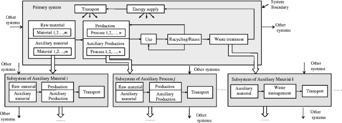
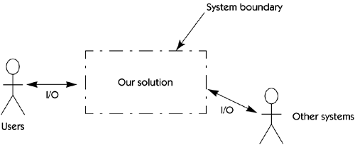
System flow diagrams, also known as process flow diagrams or data flow diagrams, are cousins to common flow charts In a system flow diagram, the goal is to present a visual representation of some component of the business model, such as a standard customer/clerk transaction at a sandwich shop window•The position of the system boundary has a profound effect on the system requirements •Defining a system boundary is a political judgment –There may be pressures to develop system boundaries that increase / decrease the influence or workload of different parts of an organization Chapter 5 System modeling 9The Boundary Diagram is used to define the system to be analysed This is done by making the necessary decisions about the location of the external interfaces Those who define interfaces by and large define the system The system definition also includes the determination of the inherent subsystems and their internal interfaces

Answered System Boundary Cooling Water Vapor Bartleby
System boundary diagram example
System boundary diagram example-The delineation of the system's boundary is in principle arbitrary, but important, as it defines the place at which the exchange fluxes take place Figure 1 shows a schematic diagram of the upper lithosphere, the land surface, the ocean, and the lower atmosphere, and the delineation of the boundary of the CZ that we use here The upper boundary is drawn just above the surface of the soil and the vegetative cover at the interface to the lower atmosphere above the canopyThe use cases enclosed in the system boundary represent the functionalities performed by behaviors (activity diagrams, sequence diagrams, and state machine diagrams) Actors may interact either directly or indirectly with the system They are often specialized so as to represent a taxonomy of user types or external systems


Q Tbn And9gctnx9kkvi1bfbpxj M0raiab2y Qwrazf4ozq354svyehopljms Usqp Cau
1 draw system boundary diagram 2 draw use case diagram (technical tool) 3 draw class diagram (technical tool) Show transcribed image text Expert Answer Previous question Next question Transcribed Image Text from this QuestionWith a defined system boundary, the organization should have a welldefined and documented diagram depicting of all of the entities that store or process system data Boundary Protection Using our outsidein approach, the next step is to review the system's boundary protection Boundary protection is the "monitoring and control of communications at the external boundary of an information system to prevent and detect malicious and other unauthorized communication" Protection is achieved– System Application Data Flow within the proposed boundary – System Application Data Flow to all Leveraged and Interconnected Systems DATA FLOWS TO UNDERSTAND Inside the Boundary Rules of Thumb 1 & 2 RULE OF THUMB 1 Federal Information that is processed, stored, or transmitted by or for the Federal Government, in any
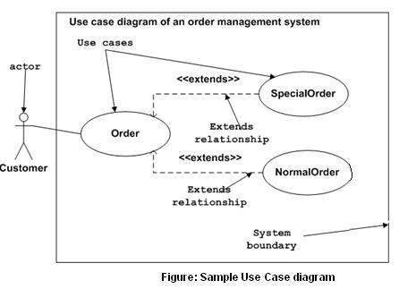
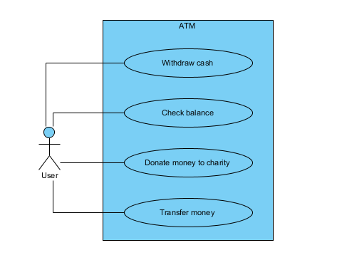
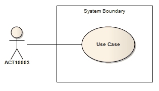
You can think of a system context diagram as a highlevel map of a system and its surrounding environment Drawing a context diagram helps you to understand how a system interacts with otherA System Boundary is the basis for the Image element, which enables you to add icons or backgrounds to a diagram, automatically displaying the Image Manager window from which to select the appropriate image;System Boundary (subject) – represents the system that owns and performs the use case on the diagram – noted by the rectangle enclosing the use cases (not the whole diagram frame boundary) Example above is the DellSat77
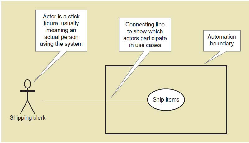
Creating a system boundary box The system boundary box must be the first element placedin a usecase diagram It distinguishes the border between use casesand actors (use cases are inside the borders of the system boundarybox and actors are outside of it) Procedure Click the Boundary box button Click once in the drawing areaThe boundary is the closed threedimensional surface that encloses the system and separates it from the surroundings The boundary may (and usually does) coincide with real physical surfaces the interface between two phases, the inner or outer surface of the wall of a flask or other vessel, and so on•The position of the system boundary has a profound effect on the system requirements •Defining a system boundary is a political judgment –There may be pressures to develop system boundaries that increase / decrease the influence or workload of different parts of an organization Chapter 5 System modeling 9


Block Diagram Fmea Boundary Diagram Automotive Apqp Dietz Consultants
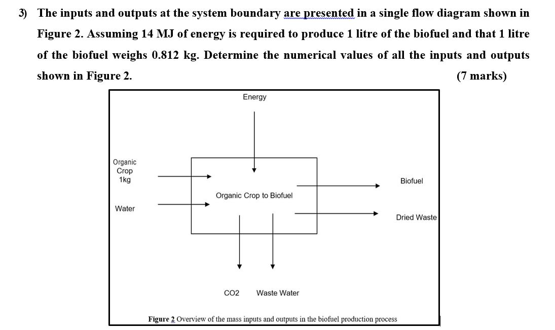


3 The Inputs And Outputs At The System Boundary A Chegg Com
– System Application Data Flow within the proposed boundary – System Application Data Flow to all Leveraged and Interconnected Systems DATA FLOWS TO UNDERSTAND Inside the Boundary Rules of Thumb 1 & 2 RULE OF THUMB 1 Federal Information that is processed, stored, or transmitted by or for the Federal Government, in anyA Context Diagram is a very simple but powerful tool for exploring the environment and boundary of a proposed system or analysing an existing one Like ALL modelling methods it has limitations The following outline these limitations and where possible propose approaches to minimise their effectYou can think of a system context diagram as a highlevel map of a system and its surrounding environment Drawing a context diagram helps you to understand how a system interacts with other


Creating An Information System Data Flow Diagram Information Security University Of Florida


Q Tbn And9gctgrslre6mm Wjshkpzlmrjf7szmewfq 8nmbnpizndng4fqq S Usqp Cau
Source(s) CNSSI under information system boundary NIST SP Rev 1 NIST SP Rev 2 under information system boundary NIST SP under Information System Boundary NIST SP Rev 1 under Information System Boundary NIST SP Rev 1 under Information System Boundary NIST SP under Information SystemThe goal of the Information System/Data Flow Diagram is to capture the main components of an Information System, how data moves within the system, userinteraction points, and the Authorization Boundary Think of this diagram as conceptual rather than technical – multiple systems can be abstracted together, and there's no need to detail every network connectionDescribing the system by grouping the use cases in the rectangle boundary, the System Boundary in Visual Paradigm provides use case containment behavior


System Diagram Designwiki


Block Diagram Fmea Boundary Diagram Automotive Apqp Dietz Consultants
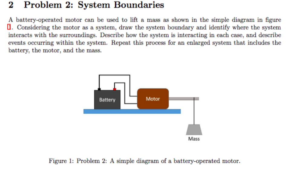
Usually we consider only one system at a time and call it simply "the system" The rest of the physical universe constitutes the surroundings of the system The boundary is the closed threedimensional surface that encloses the system and separates it from the surroundings The boundary may (and usually does) coincide with real physical surfaces the interface between two phases, the inner or outer surface of the wall of a flask or other vessel, and so onA system boundary is a boundary that separates the internal components of a system from external entities These entities can also be thought and be called as actors In a use case diagram, aServices and systems The authorization boundary accounts for the flow of all federal information and metadata through the system A cloud authorization boundary illustrates a CSP's scope of control over the system as well as any system components or services that are leveraged from external services or controlled by the customer
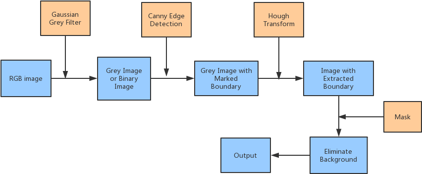


Lane Detection Procedures Lane Departure System Boundary Diagram Clipart Large Size Png Image Pikpng


The C4 Model For Visualising Software Architecture
Separating system components with boundary protection mechanisms provides the capability for increased protection of individual components and to more effectively control information flows between those components This type of enhanced protection limits the potential harm from cyber attacks and errors The degree of separation provided variesToolbox icon Learn more Use Cases;Use Case Diagram Use cases are a powerful technique for exploring user requirements The Unified Modeling Language (UML) includes a use case diagram notation Figure 2 shows a partial use case diagram for our cafeteria ordering system The rectangular box represents the system boundary, analogous to the circle in a context diagram


Sandalwood Com Wp Content Uploads 19 11 Cs Equipment Fmea Final Pdf


A Taxonomy Of Stakeholders
A System Boundary is not the same as the Boundary element used to capture user interactions in, for example, Analysis diagrams ;📚📚📚📚📚📚📚📚 GOOD NEWS FOR COMPUTER ENGINEERS INTRODUCING 5 MINUTES ENGINEERING 🎓🎓🎓🎓🎓🎓🎓🎓 SUBJECT Artificial Intelligence(AI) Database ManagementSystem Boundary Diagram ( Block Diagram) Use Creately's easy online diagram editor to edit this diagram, collaborate with others and export results to multiple image formats We were unable to load the diagram You can edit this template and create your own diagram
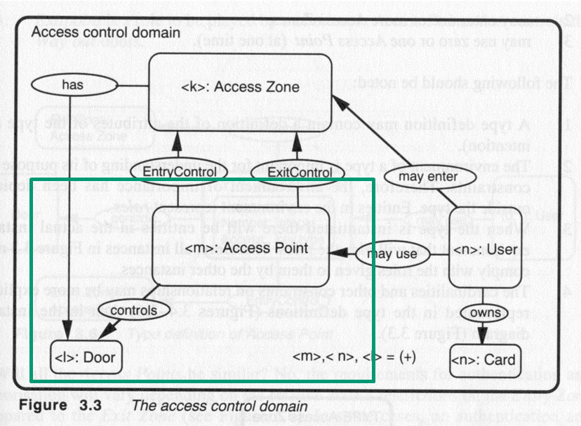


Untitled Document


System Context Diagram Wikipedia
In case of open system in thermodynamics, mass transfer across the system boundary will take place and energy may also transfer across the system boundary You will see that maximum engineering accessories or devices will follow the concept of open systemDescribing the system by grouping the use cases in the rectangle boundary, the System Boundary in Visual Paradigm provides use case containment behavior4 System Boundary Boxes The rectangle around the use cases is called the system boundary box and as the name suggests it indicates the scope of your system the use cases inside the rectangle represent the functionality that you intend to implement Indicate Release Scope with a System Boundary Box
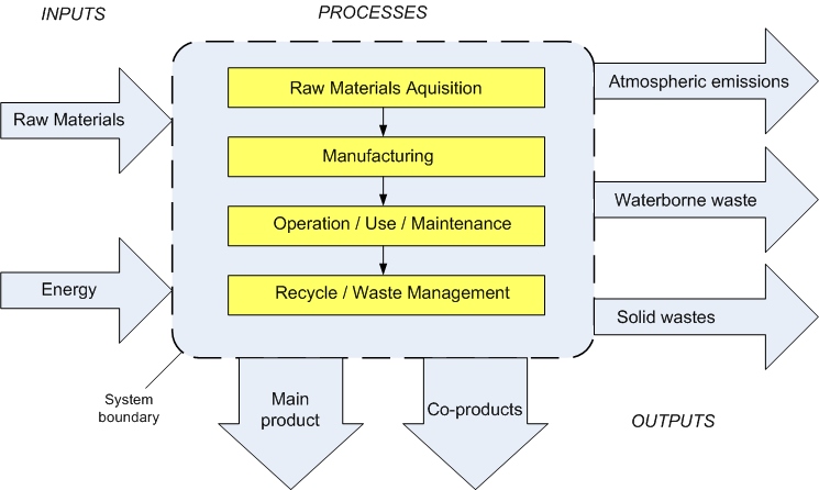


2 4 Life Cycle Assessment Eme 807 Technologies For Sustainability Systems


Developed By Sam Abihana Ion Furtuna Adithya Rajagopal Ppt Download
Eg, Login UC includes User Authentication UC) Extend relationship between Use Cases (one UC calls Another under certain condition;The system boundary defines what you will be protecting from threats and emerging vulnerabilities Choose your boundary carefully The System Boundary in Two Parts There are two important and integrated parts of a system boundary — the system boundary and the authorization boundary Here is a look at bothA clearly defined authorization boundary is a prerequisite for an effective security categorization Security categorization describes the potential adverse impacts to organizational operations, organizational assets, and individuals should the information and information system be comprised through a loss of confidentiality, integrity, or availability


Boundaries Can Be Important In System Modeling For Showing The Relationship Between Systems Distinction Overlap Hierarchy Etc System Hierarchy Chart


System Context Diagram Wikipedia
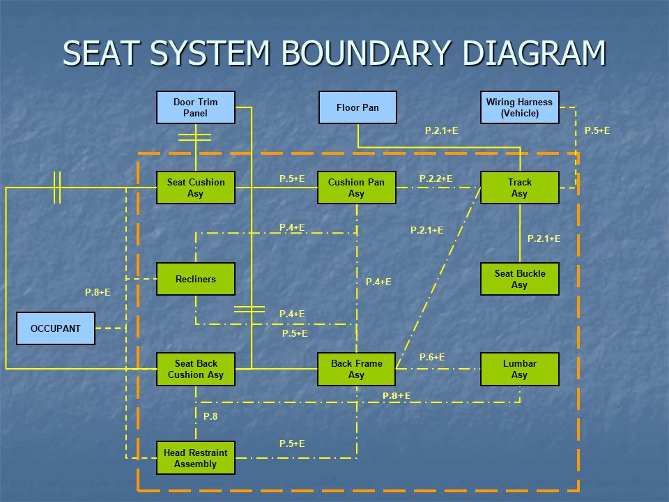
A System Boundary is not the same as the Boundary element used to capture user interactions in, for example, Analysis diagrams ;Here's the same diagram without the special icons Entities Entities are objects representing system data Customer, Product, Transaction, Cart, etc Boundaries Boundaries are objects that interface with system actors UserInterface, DataBaseGateway, ServerProxy, etc Controls Controls are objects that mediate between boundaries and entitiesOVERVIEW Boundary Diagrams are used to identify how systems, subsystems, or components interact with one or more design items contained within a defined boundary The direction and type of interactions can be defined Boundary Diagrams are usually created before a FMEA session


Section 1 5 Systems Engineering Wikibooks Open Books For An Open World


System Boundary Diagram Research Institute S Infrastructure Working Download Scientific Diagram
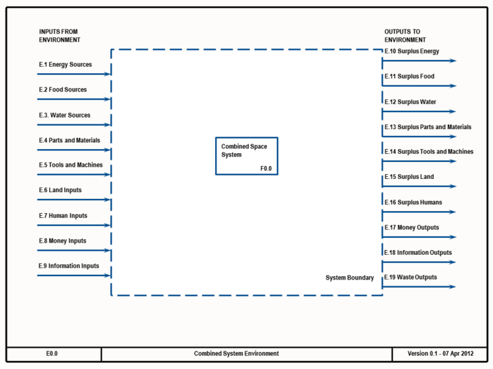
System Boundary Diagrams sometimes come up in the context of a Use Case and sometimes in the context of Software Testing Either way they are a useful in the effort expended when determining what to test While the 'normal' System Boundary Diagram shows the boundaries of the system and thus the boundaries of the testing, we try to use it only as a starting point for other diagrams that may also aid in defining the testing effort and scopeThis convention of showing the system boundary in use case diagrams was used by Jacobsen but does not typically feature in use of UML or in the Rational Unified Process We have found it worthwhile, consistent with the idea of the system as an object, and helpful in resolving issues about determining the boundary of system responsibilitiesA system context diagram (SCD) in engineering is a diagram that defines the boundary between the system, or part of a system, and its environment, showing the entities that interact with it This diagram is a high level view of a system It is similar to a block diagram


Fmea Corner Making The Fmea Scope Visible


Lane Detection Procedures Lane Departure System Boundary Diagram Clipart Pikpng
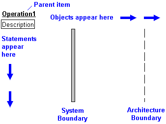
System sequence diagrams are visual summaries of the individual use cases All systems are treated as a black box;A system boundary is a boundary that separates the internal components of a system from external entities These entities can also be thought and be called as actors In a use case diagram, aA System Context diagram is a good starting point for diagramming and documenting a software system, allowing you to step back and see the big picture Draw a diagram showing your system as a box in the centre, surrounded by its users and the other systems that it interacts with


Solved 2 Problem 2 System Boundaries A Battery Operated Chegg Com


Chapter 10 Thinking Critically
Think of ifthen decision points)Answer to In detail explain how making changes to the system boundary and context boundary would impact a usecase diagram with exThe diagram places emphasis on events that cross the system boundary from actors to systems A system sequence diagram should be done for the main success scenario of the use case, and frequent or complex alternative scenarios


En Etool


How To Define Service Boundaries Hacker Noon
An FMEA boundary diagram (also called an "FMEA block diagram") is an essential input to new FMEA projects It is a visual depiction of the entire system or design to show clearly the boundaries of the FMEA analysis (what is included and not included), the interfaces between the items, and other information that can help to depict the scopeThe initial System Boundary Diagram shows the systems that are in scope and the interfaces to that system Clearly we are testing the systems that are in scope and those interfaces Unless there is a compelling reason to extend the testing, we would normally stop at that point and consider the rest to be out of scopeElements of use case diagram Other details Boundary of system Include relationship between Use Cases (one UC must call another;
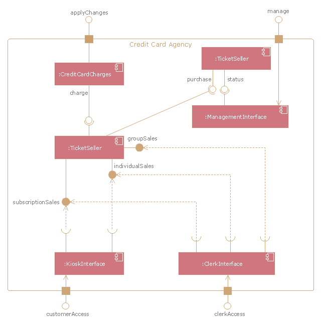


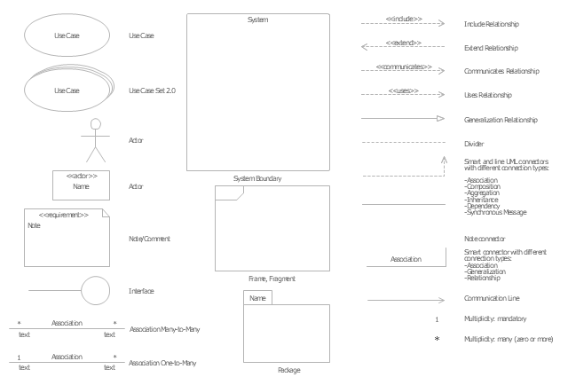
Bank Atm Use Case Diagram Uml Use Case Diagram Ticket Processing System Uml Use Case Diagram System Of Goods Selling Via Catalogues System Boundary Diagram Example


Traffic Modelling In System Boundary Expansion Of Road Pavement Life Cycle Assessment Sciencedirect
March 1 18 An authorization boundary provides a diagrammatic picture of a system's internal components to a Cloud Service Provider (CSP) along with connections to external services and systems, accounting for all Federal information and metadata that flows through a systemIn case of open system in thermodynamics, mass transfer across the system boundary will take place and energy may also transfer across the system boundary You will see that maximum engineering accessories or devices will follow the concept of open systemThe system boundary box must be the first element placed in a usecase diagram It distinguishes the border between use cases and actors (use cases are inside the borders of the system boundary box and actors are outside of it) Creating a system boundary box Creating a system boundary box
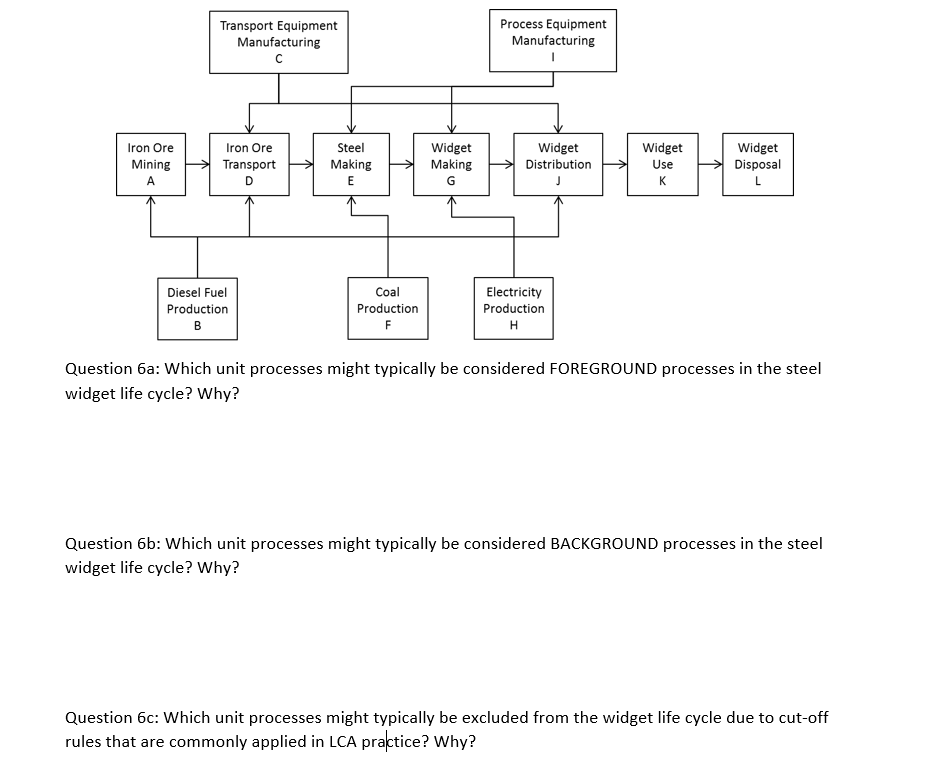


Please Show All Work And Steps Thank You System Bo Chegg Com
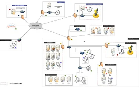


Network Diagrams For Ssp Cmmc And Nist 800 171 Cmmc Compliance
The diagram also allows a definition of the system's boundary The Use Cases are described only in terms of how they appear when viewed externally by the user (a system's behavior as the user perceives it), and do not describe how the functionality is provided inside the systemSystem Boundary ( Use Case Diagram (UML)) Use Creately's easy online diagram editor to edit this diagram, collaborate with others and export results to multiple image formats We were unable to load the diagram You can edit this template and create your own diagramA System Boundary is the basis for the Image element, which enables you to add icons or backgrounds to a diagram, automatically displaying the Image Manager window from which to select the appropriate image;
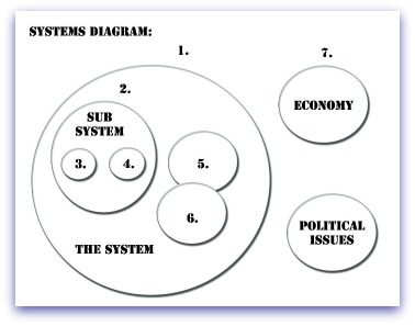


Systems Diagram


1 The System Boundary For Energy Analysis Download Scientific Diagram
Mapping Use Cases to Activity Diagrams (Online resource) Instance Classifier;


Engn2225 Oc System Boundary Chart Youtube


System Boundary Diagram Of The Life Cycle Assessment Download Scientific Diagram
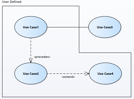


System Boundary Properties Enterprise Architect User Guide


Uml 2 Use Case Diagrams An Agile Introduction
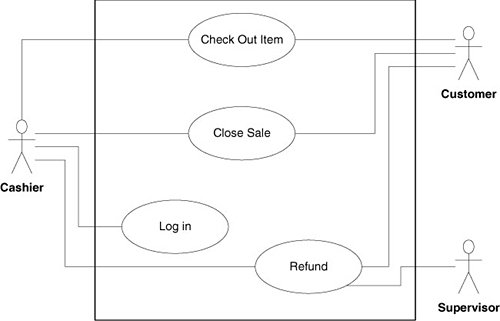


Diagramming Use Cases Agile Principles Patterns And Practices In C


System Boundary Diagram For Electric Powertrain Download Scientific Diagram


Creating An Information System Data Flow Diagram Information Security University Of Florida
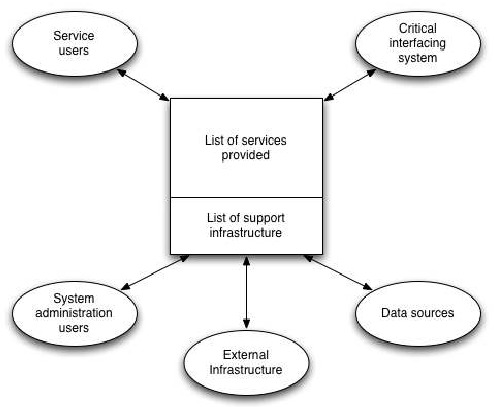


File System Boundary Diagram Png Wikimedia Commons


System Boundary For Embodied Energy In Buildings A Conceptual Model For Definition Sciencedirect


Http Www Task42 Iea Shc Org Data Sites 1 Publications T44a38 Rep B1 Shp Perf Definition approved Pdf


System Context Diagram Wikipedia


Boundary System It Page 1 Line 17qq Com


Cybersecurity Architecture Part 2 System Boundary And Boundary Protection


Block Diagram Fmea Boundary Diagram Automotive Apqp Dietz Consultants


Q Tbn And9gctnx9kkvi1bfbpxj M0raiab2y Qwrazf4ozq354svyehopljms Usqp Cau
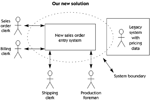


Step 4 Define The Solution System Boundary Managing Software Requirements C A Use Case Approach


Uml Use Case Diagrams Tutorialspoint


Http Www Task42 Iea Shc Org Data Sites 1 Publications T44a38 Rep B1 Shp Perf Definition approved Pdf


Fmea Block Diagrams Boundary Diagrams


Ins Das 23 Architecture For The Ultradas Overview


Autonomous System Boundary Router Device And Method For Acquiring Virtual Private Network Label Diagram Schematic And Image 03


Autonomous System Boundary Router Device And Method For Acquiring Virtual Private Network Label Diagram Schematic And Image 02


Overview Of Sequence Diagrams


Expressing Multiple Projects Using System Boundaries Use Case Diagram Template


Object Oriented Analysis And Design 3 4 Use Case Diagram Programmer Sought


Creating An Information System Data Flow Diagram Information Security University Of Florida


Defining Project Scope What S In What S Out By Karl Wiegers Analyst S Corner Medium


Generic System Boundary Diagram Download Scientific Diagram


Www Jstor Org Stable


System Boundary An Overview Sciencedirect Topics


What Is A Context Diagram Ppt Download


A System Boundary Identification Method For Life Cycle Assessment Springerlink


Expanding The Use Of A Use Case Diagram Why Change


What S Use Cases Diagram Learn Information System


Www Jstor Org Stable


Sflow System Boundary


Boundary Diagram Block Boundary Diagram Template


2 2 Lca Lcia Concepts Chemistry Libretexts


Q Tbn And9gcq0boxuoivpviz9rs4xoj72 Yzwpeufmfg2 Ccdnhix16mssuzn Usqp Cau


Safety Concept Diagram Astah


System Boundary Use Case Modeling Uml Case Tool


Q Tbn And9gcr4oljguag8jcpfxzsbvpkam7qwpy Ets95axieguw1ydzbebyi Usqp Cau


Design Elements Uml Use Case Diagrams Uml Component Diagram Credit Card Agency Bank Atm Use Case Diagram System Boundary


System Boundary Diagram Editable Diagram Template On Creately


Explicit System Boundary Solid Line Vs Implicit Diagram Png Free Transparent Png Images Pngaaa Com


Pdf Definition And Identification Of System Boundaries Of Highly Automated Driving Semantic Scholar


What Are The System Boundaries Of Etoollcd Etool


System Boundary Enterprise Architect User Guide


Solved Modelio 3 1 1 Use Case Diagram Subsystem Missing Modelio Forum


Define System Boundary General Questions Discussions Discuss The Visual Paradigm


Use Case Diagram Uml 2 Tutorial Sparx Systems
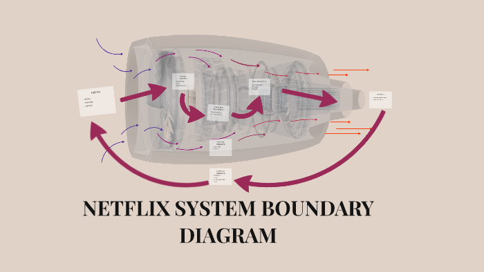


Netflix System Boundary Diagram By Jon Browning


Fmea Corner Making The Fmea Scope Visible


File System Boundary Diagram Of Volunteer Tracking System Png Wikimedia Commons
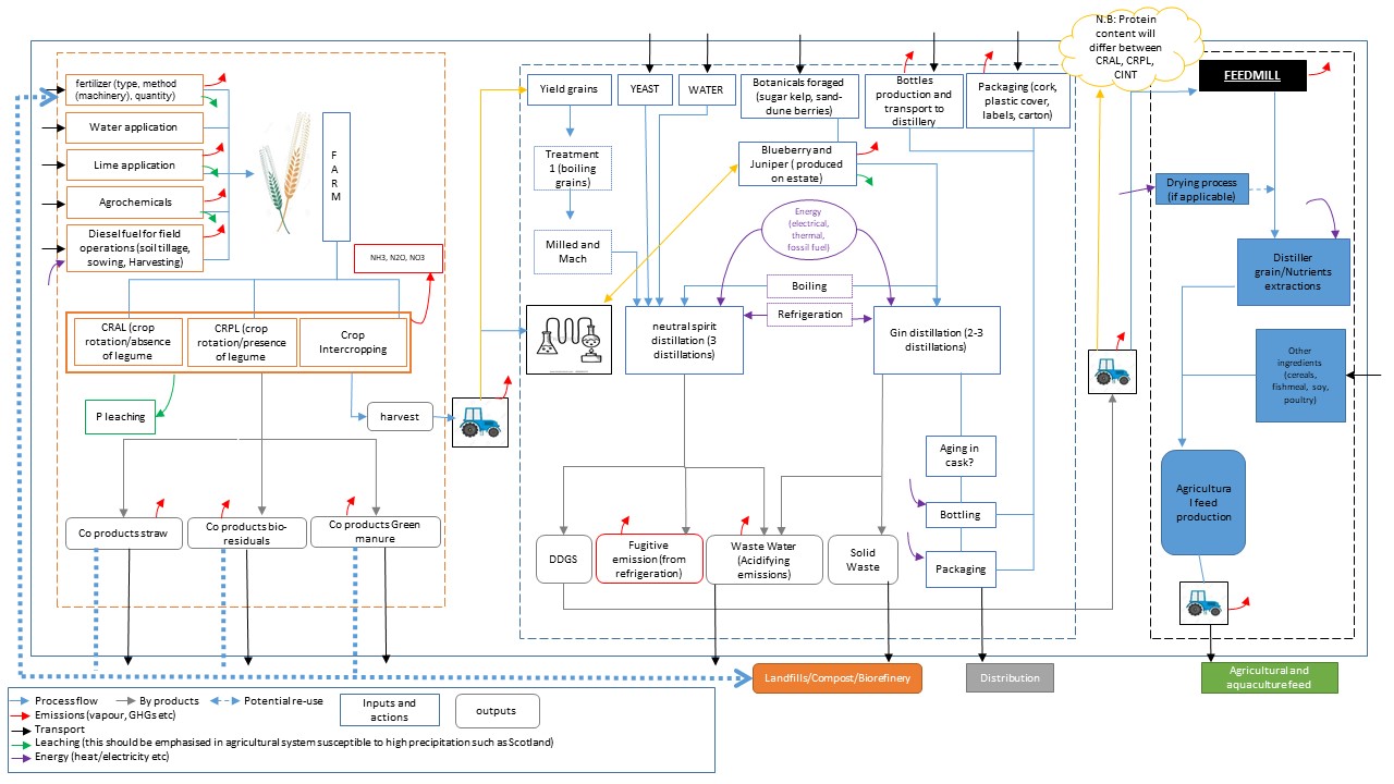


Our Value Chain System Boundary Cradle To Gin Gate To Feed Gate This Is Only A Temporary Draft Theophile Lienhardt


Block Diagram Fmea Boundary Diagram Automotive Apqp Dietz Consultants


Answered System Boundary Cooling Water Vapor Bartleby


Archived Pollution Prevention Planning Handbook Pollution Prevention Planning
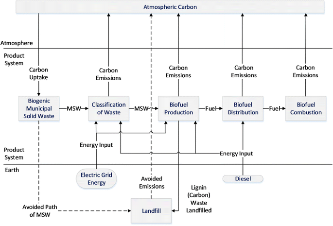


Attributional And Consequential Life Cycle Assessment In Biofuels A Review Of Recent Literature In The Context Of System Boundaries Springerlink


The C4 Model For Visualising Software Architecture


The Entity Control Boundary Pattern


Uml 2 Use Case Diagramming Guidelines


Www Reliasoft Com Images Documents Xfmea risk discovery drives system fmea plan Reliasoft Pdf
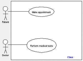


Elements Of A Use Case Diagram Geog 468 Gis Analysis And Design


System Boundary In Use Case Diagram Model System Boundary Symbol System Boundary Examples Youtube


System Boundary Diagram For Electric Powertrain Download Scientific Diagram


Use Case Diagram For Data Collection Software Engineering Stack Exchange


System Diagram Designwiki


Step 4 Define The Solution System Boundary Managing Software Requirements C A Use Case Approach


Wired For Safety For Organization S Cybersecurity Start With System Boundary And Inventory Vtdigger


Gate To Gate System Boundary And Process Flow Diagram Of Briquetted Download Scientific Diagram


Http Users Abo Fi Rzevenho Ptg14 Oh2 Pdf


Http Csis Pace Edu Marchese Cs3 L9 Use case diagrams Pdf


System Of Interest Archives Systems Thinkers Anonymous


コメント
コメントを投稿